From PTFE Chemistry to ePTFE Performance
Polytetrafluoroethylene (PTFE) is renowned for its excellent chemical stability, wide service temperature range, electrical insulation properties, low friction, and anti-stick characteristics. It has one of the lowest coefficients of friction and the lowest surface energies among solid materials, which means it adheres to virtually nothing. The repeat unit of PTFE is represented by (C₂F₄)ₙ. In the polymer chain, the CF₂ groups adopt a zig-zag conformation; due to the larger size of fluorine atoms compared to hydrogen, adjacent CF₂ units cannot maintain an ideal trans arrangement, resulting in a helical, twisted chain. Fluorine effectively shields the carbon backbone, and the C–F bonds possess high bond energy, leading to weak intermolecular forces between the F–C chains. Because of fluorine’s high electronegativity and strong steric shielding, PTFE chains do not readily entangle with other materials, which explains PTFE’s anti-fouling, self-cleaning, and non-stick properties.
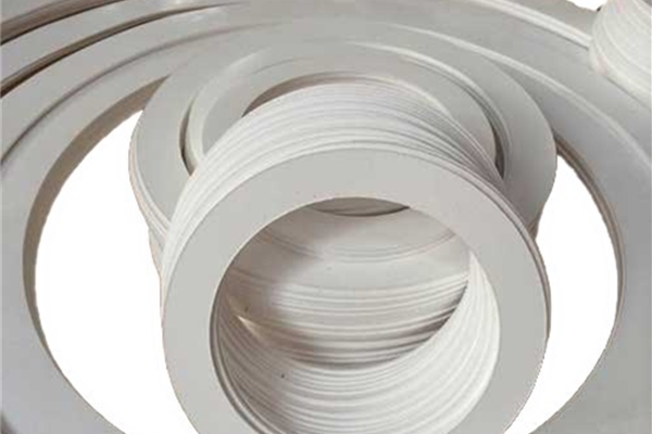
PTFE microporous membranes inherit these characteristics and additionally provide water repellency, wind resistance, moisture vapor transmission, air permeability, and charge stability. They are effectively used in protective garments, baghouse filters, and architectural daylighting (for example, in large venues that utilize PTFE membranes). Additionally, they serve widely as sealing media in aerospace, machinery, electrical and electronics applications, and petrochemical equipment.
However, pure PTFE also presents challenges that can limit its application in structural sheets. These challenges include susceptibility to wear, high thermal expansion, pronounced creep, and low load-bearing capacity. Its symmetric chain and lamellar crystallites tend to shear and flake. Moreover, due to PTFE’s non-stick nature, fibers and fillers bond poorly to the matrix. As a result, pure PTFE sheets may struggle to deliver the necessary tie strength, rigidity, and creep resistance required for demanding seals.
A Multifunctional Expanded PTFE Sheet: What It Is and Its Application
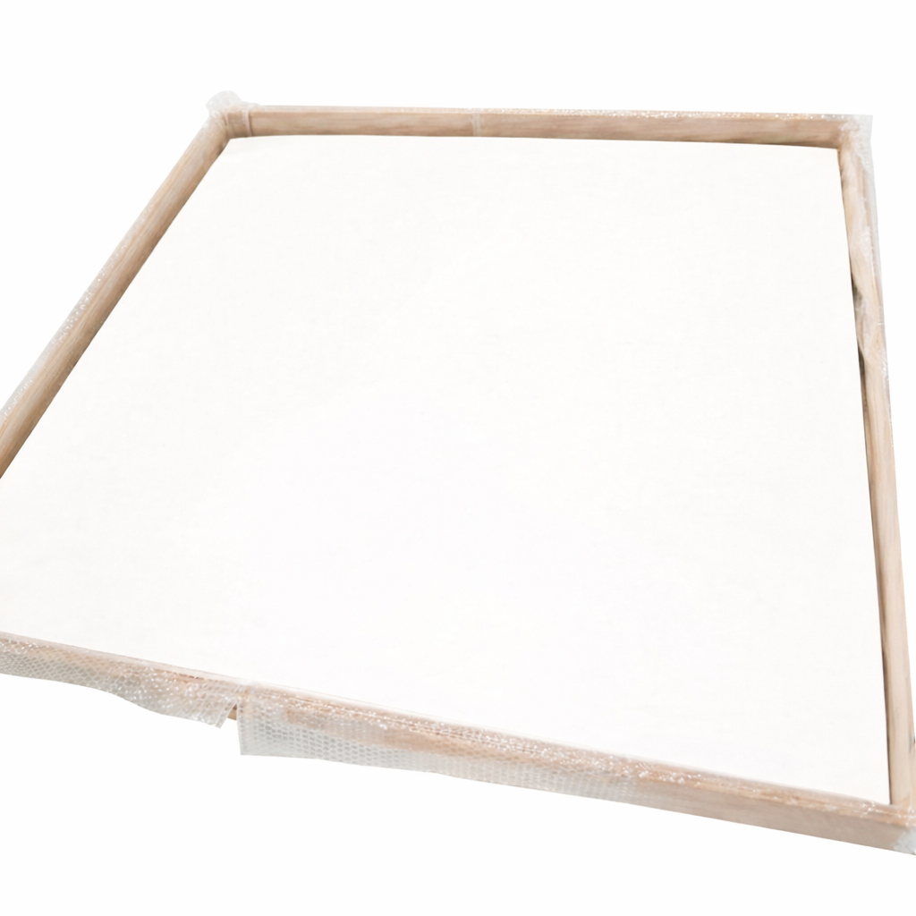
To overcome these limitations while maintaining PTFE’s key strengths, we present a multifunctional expanded PTFE (ePTFE) sheet and an efficient laminated composite process. The approach keeps manufacturing cost low and processing simple, yet delivers a sheet with reliable sealing, chemical and thermal stability, excellent electrical insulation, plus enhanced creep resistance, higher tie strength, and antibacterial functionality.
Formulation and Process Overview: The process begins with a homogeneous mixture of PTFE resin, a PTFE modifier, fibers, titanium dioxide (TiO₂), and an organic solvent. This mixture is then pre-pressed to form a billet.
The billet undergoes an extrusion process to create a rod, which is subsequently calendered using a twin-screw extruder into a film. The organic solvent is removed by heating, and the film is stretched both transversely and longitudinally to produce a microporous PTFE membrane.
Multiple membranes are then laminated together and sintered to create a high-tensile expanded PTFE sheet.
The PTFE modifier is produced by replacing at least one fluorine atom with hydrogen in a PTFE-family polymer, with polyvinylidene fluoride (PVDF) being the preferred choice.
For the PTFE to modified PTFE (hydrogen to fluorine) system, a molar ratio of 1:3 to 1:5 is recommended.
Reinforcement fibers may include glass fibers and/or carbon fibers.
Possible solvent options include solvent naphtha, petroleum ether, or aviation kerosene.
.
The Expanded PTFE Sheet Processing Steps
1, Raw-material mixing: PTFE, the PTFE modifier (e.g., PVDF), fibers, TiO₂, and solvent are mechanically mixed to uniformity.
2, Pre-pressing: Load the mix into a cylindrical preform mold; close the mold and press. Increase pressure gradually to the setpoint, hold for several minutes, then release and demold a cylindrical green billet.
3, Extrusion: Extrude the preform through a suitable die to obtain fine rod-like extrudate.
4, Calendar to film: Convert the rods to a thin film using a twin-screw calender.
5, Drying: Pre-heat the film at an elevated temperature to remove part of the organic solvent.
6, Stretching & heat treatment: Heat and perform multiple transverse stretches and sequential bi-axial stretching/fixing. After high-temperature pre-sintering, remove all residual solvent to obtain a single-layer PTFE microporous membrane (typically 0.05–0.5 mm thick).
7, Lamination: Laminate and sinter multiple membranes to yield the final ePTFE sheet.
Optional surface plasma treatment (after step 5). Irradiate the dried film with plasma for 1–3 hours to replace part of the surface fluorine with hydrogen on both PTFE and the PTFE modifier. This raises surface adhesion, improving fiber wet-out and interlayer bonding during stretching and lamination.
Preferred ratios and conditions (illustrative). In step (1), a mass ratio of PTFE: modified-PTFE: fibers: TiO₂: solvent = 5: 2 : 1: 1: 1 is effective; maintain the H: F molar ratio within 1 : 3–5. In step (2), a representative pre-press setting is 4 MPa for 10 min.
Why the Design Works
Matrix–Fiber Compatibility by Design:
Adding fibers alone (either glass or carbon) can, paradoxically, reduce stretchability during membrane formation. At low draw, films do not elongate easily, while at high draw, the fibers are prone to breaking. More importantly, PTFE’s non-stick surface does not bond well with the fibers, which can lead to debonding or even fracturing during stretching, ultimately failing to deliver the desired tie strength. We address this issue by introducing PVDF as a modifier within the PTFE family. Compared to PTFE, PVDF has two fluorine atoms replaced by hydrogen atoms; the smaller size and lower electronegativity of hydrogen enable better chain entanglement and adhesion. When melted, PVDF encapsulates the fibers and TiO₂, cushioning them during stretching, reducing fiber breakage, and enhancing the tie strength of the sheet.
Surface Activation for Bonding:
Plasma treatment further replaces surface fluorine with hydrogen, which raises the surface energy and improves interfacial adhesion. These added adhesion buffers help distribute forces during bi-axial stretching, resulting in improved tensile strength, elongation at break, and creep resistance in the finished sheet.
The Role of TiO₂ (Titanium Dioxide):
TiO₂ provides antibacterial and deodorizing properties. It also enhances lubrication during processing, reducing friction-induced roughness, improving surface smoothness, and minimizing calendering cracks. As a result, we achieve a smoother, denser, and more uniform expanded PTFE laminate, which offers greater functional value in hygienic and high-purity environments.
Net Result for Seal Designers:
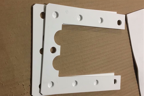
The laminated expanded PTFE sheet offers:
Reliable sealing with chemical and thermal stability, and excellent electrical insulation.
Improved creep resistance and higher tie strength under clamping loads.
Antibacterial functionality (thanks to TiO₂), which is beneficial for pharmaceutical, food, and high-purity applications.
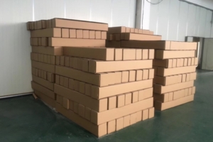
A process that remains cost-effective and scalable for industrial bulk supply.
Where to Use It—and What to Specify
This expanded PTFE sheet is suitable for gaskets and seals, pump/valve diaphragms, manway and cover liners, chemical barrier layers, and filtration/support laminates in petrochemical, refining, chemical processing, power generation/steam, semiconductor, utilities, pharmaceutical/bioprocess, food & beverage, and water treatment applications. It is compatible with strong acids and alkalis, solvents, hydrocarbons, steam/water, and other aggressive media within the validated temperature envelope.
When sending an RFQ, include the following details: media, temperature/pressure (and cycling), flange or clamping standard, target compressibility/recovery, thickness, fiber choice (glass or carbon), antibacterial requirement (TiO₂), and any plasma-treated surface requirements. We’ll return a grade recommendation, lamination stack, and processing notes aligned with your ASME/EN/JIS practice