PTFE: Structure and Key Properties
Polytetrafluoroethylene (PTFE) is a fluorinated polymer whose main chain contains fluorine atoms. In the PTFE molecule, F atoms shield the C–C bonds and the C–F bond has very high bond energy and extraordinary stability. Except for molten alkali metals and elemental fluorine, PTFE is not attacked by chemical reagents. The F atoms are symmetrically arranged; C–F bonds are covalent, and there are no free electrons in the molecule—so the whole molecule is electrically neutral, giving PTFE excellent dielectric performance. An inert fluorinated outer shell provides outstanding non-stick behavior and a low coefficient of friction.
PTFE offers an exceptional combination of properties: high-temperature resistance, chemical resistance, non-stick, self-lubricating, excellent dielectric performance, and very low friction. When fillers that can withstand PTFE sintering temperatures are added, its mechanical properties can be greatly improved while preserving PTFE’s other advantages. Typical fillers include glass fibers, metals, metal oxides, graphite, molybdenum disulfide, carbon fibers, polyimide, EKONOL, etc. Wear resistance and the limiting PV value can increase by up to 1000×.
PTFE Gasket Product Range
In China, PTFE-based sealing gaskets are commonly produced in two categories:
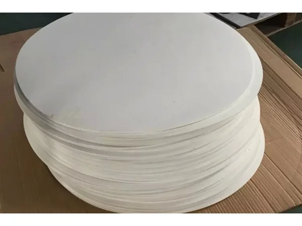
Virgin PTFE gaskets: either molded sheets produced directly from suspension PTFE by molding, or skived sheets produced by cutting/turning PTFE sheets (or rods). Molded sheets often have non-uniform density and lower softness; skived sheets have relatively uniform density but, due to the processing method, present a curling tendency that is unfavorable for installation.
Modified PTFE gaskets: functional materials are blended into PTFE resin to compensate for the shortcomings of virgin PTFE. These products are mostly small-size sealing elements formed by direct molding.
Seeking a superior sealing material is therefore a significant technical objective—expanded PTFE (ePTFE) is exactly such a new material.
Expanded PTFE in Medicine
Expanded PTFE (ePTFE) is a new medical polymer produced by stretching PTFE resins via special processes. It is white, elastic, and flexible, with a node-and-fibril micro-network. These fine fibrils create innumerable micropores, allowing ePTFE to bend freely (over 360°). It shows excellent blood compatibility and resistance to biological aging, and is used in vascular grafts, cardiac patches, and other medical products. Medically, it is regarded as an ideal substitute for biological tissue: thanks to its biocompatibility and unique microporous structure, it is non-toxic, non-carcinogenic, and non-sensitizing, and tissue cells and blood vessels can grow into its pores, forming tissue connections similar to autologous tissue.
In plastic surgery, the commonly named “expanded material” refers to expanded polytetrafluoroethylene surgical soft-tissue patch (expanded PTFE, e-PTFE). Its chemical structure is a carbon chain encapsulated by fluorine atoms. Due to its unique molecular structure, expanded PTFE is extremely stable. Over 40 years and 6 million clinical applications—including vascular grafts, dural substitutes, and cardiac patches—have reported no rejection, proving excellent biocompatibility. Produced from PTFE dispersion resin by special processes, it has an ultra-micro “node and fibril” structure; by controlling node spacing, host tissue ingrowth can be induced. Unlike silicone rubber (which heals by fibrous encapsulation), ePTFE heals by tissue ingrowth, delivering natural appearance, no implant migration or degeneration, and fewer complications. Because the volume of ingrown tissue is limited, removal—if required—is not overly difficult.
Expanded PTFE in Industry
Industrial expanded PTFE is a pure PTFE engineered via special processing to create multi-directional fibrils and a closed microporous structure. Porosity ranges 40%–97% with pore size 0.25–0.5 μm. It retains PTFE’s superb chemical stability, extremely low friction, wide service temperature, excellent aging resistance, non-toxicity, and non-polluting nature. Its fine, soft yet tough fibers solve the classic PTFE sealing issues of creep and cold flow. Under compression, the high-density fibrillar network entangles further, forming a tighter, more uniform, impermeable and leak-resistant structure. Even in harsh corrosive environments, it maintains excellent conformity—solving long-standing technical challenges in chemical and petroleum processing.
The Industry Need. Our Innovative Expanded PTFE Sheet Process
Domestic capability to produce pure expanded PTFE sheets remains weak, lacking a complete process and full equipment set to satisfy large-scale industrial demand.
This article details a complete production process and dedicated equipment for expanded PTFE sheets. The core concept: cold-store PTFE dispersion resin, sieve, add aids at set ratios, age the blend, form billets, extrude into rods, calender into films, degrease–dry–stretch, then perform longitudinal and transverse stretching. Bi-axially stretched films are stacked and laminated into boards, then edge-trimmed to final size.
The resulting expanded PTFE sheets mark a breakthrough over traditional methods, solving creep and cold-flow issues. Compressive resistance, creep relaxation, compressibility, and resilience are all significantly improved. Applications span aerospace, medical, food, and oil pipeline sealing, with excellent temperature performance, anti-aging, non-toxic and non-polluting characteristics.
Step-by-Step Manufacturing Process
Cold storage & sieving
Store PTFE dispersion resin below 18 °C for ≥12 h, then sieve.
Additive dosing & mixing
Inject a defined proportion of aids into the sieved dispersion resin and mix.
Mass ratio (resin: aids) = 70–80: 20–30.
Aging
Age the blended raw materials at 45–75 °C for 12–72 h.
Billet forming & secondary aging
Press the aged mix into a cylindrical billet, then age for 5–10 h.
Pressing pressure: 2.5–5 MPa; hold pressure 1–5 min after forming.
Rod extrusion
Extrude the cylindrical billet into a round rod.
Extrusion pressure: 5–7 MPa; compression ratio 100–150; temperature 45–75 °C.
Calendering
Calender the round rod into sheet-like film.
Degreasing, drying & pre-stretch
Degrease, dry, and stretch to semi-finished film at 200–280 °C.
Film line speed 10–12 m/min; draw ratio 1.1–1.2×.
Longitudinal stretching
Longitudinally stretch the semi-finished film at 200–280 °C.
Feed 1.5–2 m/min; take-up 8–16 m/min; draw ratio 5–8×.
Transverse stretching
Preheat 120–150 °C → Expansion 200–250 °C → Setting 300–380 °C.
Speed 12–20 m/min; transverse draw ratio equals longitudinal draw ratio.
Stacking & lamination
Stack multiple stretched films and laminate:
Preheat 200–250 °C for 3–5 min → Degas 350–380 °C for 15–25 min → Cool to 80–100 °C → Final set 80–100 °C, press 1–2 min.
Edge trimming
Trim edges to complete the sheet.
Specialized Equipment Set
1, Automatic mixer – frame, mixing drum with symmetric guide rollers, motor/drive, and a gas–liquid spray device: nozzles inside the drum connect to a metering tank; the tank connects to an aid reservoir and pump; the nozzle connects to the pump.
2, Aging ovens – for primary and secondary aging.
3, Billet former – fixed frame with a barrel forming the billet cavity; movable rams on both sides; cylinders on both ends drive pushrods; pushrods carry magnetic rings; the frame has magnetic sensors for alignment.
4, Rod extruder – machine frame with an insulated oil bath barrel; extrusion cylinder; cone guide and die facing the floor; a turntable aligned to the die. A movable ram faces the opposite side; a cylinder and pushrod drive the ram.
5, Calender – base with unwind, calender rolls, and rewind; a guide plate aligns with the unwind position.
6, Degrease–dry–stretch line – unwind, degreasing oven (connected to an aid-recovery system), buffer drying, stretch oven, and rewind; each section includes multiple rollers.
7, Longitudinal stretching unit – longitudinal feed, heating oven (enclosure, heating system, and twin-cone curved rolls with ellipsoidal drums), buffer cooling, and take-up; each section includes multiple rollers.
8, Transverse stretching unit – insulated housing with heating system and a chain drive. Clamps are evenly spaced on the chain to hold films; a closing mechanism at the infeed and an opening mechanism at the outfeed actuate the clamps. The housing is divided into preheat, expansion, and setting zones. Conveyor chains run parallel in preheat, diverge through expansion, and converge toward the take-up in setting.
9, Stacking/lamination station – worktable with movable fixtures; lay-up section (unwind plus reciprocating spreader for continuous lay), degassing/forming section (heated enclosure with degassing rolls), and final setting section with a press plate to compress and fix the ePTFE sheet.
10, Edge trimmer – for final trimming.
Performance & Sealing Benefits of the Produced Expanded PTFE Sheets
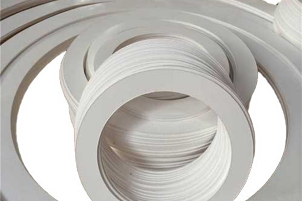
The expanded PTFE sheets produced by this process achieve international leading standards in tensile strength, elongation at break, compressibility, recovery, and sealing leak rate. They possess intrinsic anti-creep and anti-cold-flow characteristics, are easy to cut, easy to install, and offer long service life. Except for very few chemicals, they are non-reactive, making them suitable for any chemical sealing application up to 600 °F (315 °C).
These large-area, flexible sheets can be formed by mechanical punching or hand cutting—the cutting method does not affect sealing performance. Regardless of flange face geometry, installation is simple. ePTFE Gaskets made from these sheets offer unique conformability, achieving excellent seals on rough or damaged flanges without substantial extra bolt load, significantly extending flange life. As the ultimate replacement for asbestos gaskets, expanded PTFE sheet gaskets combine all the advantages of PTFE with essential resistance to creep and cold flow—critical characteristics for sealing products—while remaining easy to cut, easy to install, and applicable across nearly all sealing scenarios.