Overview
Polytetrafluoroethylene (PTFE) has a distinctive helical molecular conformation. In a PTFE molecule, fluorine atoms form a helical “shell” encapsulating the carbon backbone. This inert perfluorinated helix shields the PTFE main chain from chemical attack. Owing to this structure, PTFE exhibits exceptional chemical stability, corrosion resistance, broad high/low temperature capability, and aging resistance. It is often called the “king of plastics,” widely used across chemical processing, textiles, medical, machinery, and aerospace.
However, PTFE also shows limited creep resistance, modest compression recovery, wear sensitivity, and relatively low mechanical strength, constraining its use in more demanding services. To address these limitations and improve overall performance, PTFE is commonly modified. Typical routes include filling, surface modification, blending, and expansion. In recent years, expanded PTFE (ePTFE) has advanced rapidly. Although the structure is altered versus PTFE, ePTFE retains PTFE’s intrinsic advantages while markedly improving creep resistance and wear behavior—broadening application scope.
This article introduces ePTFE preparation methods—mechanical stretching, spinning, and porogen (pore-former) techniques—and surveys key ePTFE applications.
1. Preparation of ePTFE
1.1 Stretching Method
The stretching method was pioneered in the 1980s (widely associated with Gore) and remains the primary industrial process for ePTFE.
Process outline
Mixing – PTFE resin is blended with a liquid extrusion aid (lubricant) at a defined ratio.
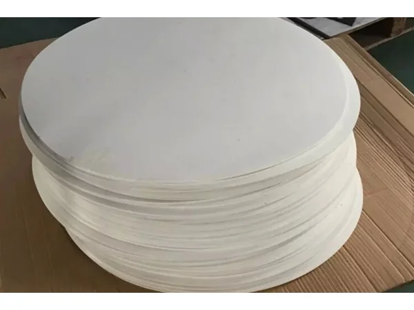
Preform – The paste is compacted at relatively low pressure into a preform, then ram-extruded to create a pre-shaped billet and calendered into sheets.
Debinding – The lubricant is removed by controlled heating.
Stretching – At set temperature(s), the sheet is uniaxially or biaxially stretched. During stretching, part of the resin is drawn into fibrils while nodes form where fibrils diverge and interconnect, creating the hallmark node-fibril microporous network of expanded PTFE.
Heat setting – Above PTFE’s melt point, the microstructure is stabilized, then cooled to ambient to obtain ePTFE.
The extrusion aid reduces friction between resin particles and equipment; preforming removes trapped air to densify the mass; extrusion and calendering raise green strength and introduce initial orientation; stretching builds the node-fibril network and porosity.
Structure–process sensitivities
Small process differences strongly affect ePTFE morphology and performance. SEM, DSC, and XRD studies show porosity, pore size, and crystallinity correlate directly with stretch ratio, stretch rate, and cooling schedule.
Our own observations on biaxial stretch ratio and line speed indicate:
Increasing transverse and longitudinal draw ratios and higher heat-set temperatures increase both open-area and average pore size.
Increasing transverse draw speed increases porosity while reducing average pore size.
By tuning biaxial stretch rates, we can effectively control fiber formation rate, microporous membrane thickness, and ultimately produce high-porosity PTFE membranes.
Example (PTFE resin: processing oil = 80: 20 by mass): specimens prepared at different total stretch ratios showed:
(1) Higher stretch ratios → fewer spherulitic clusters, more fibrils, higher porosity.
(2) As the stretch ratio increases, Poisson’s ratio decreases.
(3) Under non-isothermal crystallization, a higher stretch ratio leads to lower crystallization enthalpy and longer half-crystallization time.
1.2 Porogen (Pore-Former) Method
A porogen is a sacrificial additive used to create pores. The porogen is mixed homogeneously with the PTFE precursor, a green body is formed, and the porogen is subsequently removed (typically by sintering or chemical leaching), leaving a controlled pore structure.
Examples: ZnAc₂ and NaCl as porogens: salts are dissolved and co-processed with PTFE dispersion, then the cast film is dried (to remove water), cured at ~370 °C, and finally leached (e.g., 1 M acetic acid) to remove salts, yielding films of ~100–200 nm pore size and thickness 10 ± 2 µm.
We have also used a polycyclic aromatic porogen (C₈H₁₀) via mold-press + sinter, producing uniformly microporous PTFE sheets with high compressibility, strong recovery, and low creep-relaxation, outperforming pure molded PTFE and approaching international benchmarks.
Other work has used BaCl₂ as a porogen, later dissolved in water after sintering to generate porosity.
Selection matters
ePTFE performance is tightly linked to porogen chemistry and loading. The choice and dose affect not only expansion effectiveness but also PTFE forming behavior. In our trials with various porogens (e.g., KCl), higher porogen content reduces density, increases porosity, and lowers Shore hardness. With KCl at ~45 wt%, we measured compressibility ~89.30% and recovery ~82.12%, achieving the best elastic recovery in our series.
1.3 Spinning (Fiber) Methods
Electrospinning is frequently used to produce expanded PTFE fibrous porous membranes. Using ultra-high-molecular-weight PEO as a carrier, we co-spun PEO/PTFE and then thermally removed PEO to obtain high-temperature, chemically resistant ePTFE membranes. We also fabricated super-hydrophobic and oleophobic ePTFE films via coaxial electrospinning.
Unlike stretched films (pores formed by node-fibril networks), electrospun membranes form pores through fiber stacking. Electrospinning makes membrane thickness, porosity, and fiber diameter relatively easy to control; however, additives used during spinning must later be removed to achieve pure PTFE.
Emulsion spinning is another route: PTFE dispersion is mixed with viscose or PVA solution to create a dope for dry/wet spinning. The formed fibers are dried and sintered to remove the carrier and then stretched to obtain a fibrous membrane. Downsides include high carrier usage, higher loss, and lower dope stability.
2. Applications of expanded PTFE
2.1 Waterproof–Breathable Laminates
Expanded PTFE membranes laminated into textiles are widely used in military and consumer gear—hailed as “the fabric of the century.” Typical constructions are 3-layer laminates with nylon or polyester face fabrics, a warp-knit tricot liner, and ePTFE membrane in the middle.
Why waterproof & breathable?
Low surface energy → large water contact angle (≫ 90°) → strong hydrophobicity.
Micropores ~2 µm: ~5,000× the diameter of water vapor molecules, but ~1/200 of a water droplet, so vapor passes; liquid water does not.
Random pore distribution also confers wind resistance and improved abrasion performance.
Expanded PTFE fibers provide high strength, low shrinkage, non-stick behavior, and UV resistance—ideal for outdoor apparel, firefighting suits, space suits, surgical gowns, combat uniforms, sleeping bags, and lightweight tents.
2.2 Architectural Membranes
High-strength ePTFE films are also used in architectural applications. Unlike many architectural textiles, ePTFE offers high light transmittance and flexibility. Lighting designers leverage its optical characteristics to enhance aesthetics; multi-color transmission/reflection is used indoors. ePTFE fibers do not suffer bending damage, enabling retractable or temporary structures.
The non-stick surface imparts self-cleaning: rain washes away dirt; if needed, mild soap + water + light remove residues. With long service life, ePTFE is chosen for the daylighting roofs of iconic venues such as China’s National Stadium (“Bird’s Nest”) and Water Cube, and the U.S. Minneapolis stadium.
2.3 Membrane Distillation (MD)
MD uses a hydrophobic microporous membrane with a vapor pressure gradient across the membrane. ePTFE’s chemical resistance, thermal stability, and thermal conductivity make it an ideal MD material. Performance depends on porosity, wall thickness, and pore size.
We prepared four ePTFE hollow-fiber membranes with different wall thicknesses and pore sizes (by tuning extrusion and stretching), assembled modules, and performed Vacuum Membrane Distillation (VMD) for concentrated seawater. Findings:
Thinner walls, higher feed temperature, larger pores, higher feed flow, and higher vacuum → higher water flux.
Water flux decreases as the concentration factor increases.
Salt rejection remained > 99.5% across all operating conditions.
We also treated acidic heavy-metal solutions by MD with ePTFE hollow fibers. Post-test characterization showed no phase change, some pore enlargement, new weak –OH absorption in IR, no loss of surface hydrophobicity, and no change in tensile properties—demonstrating excellent stability in acid MD service.
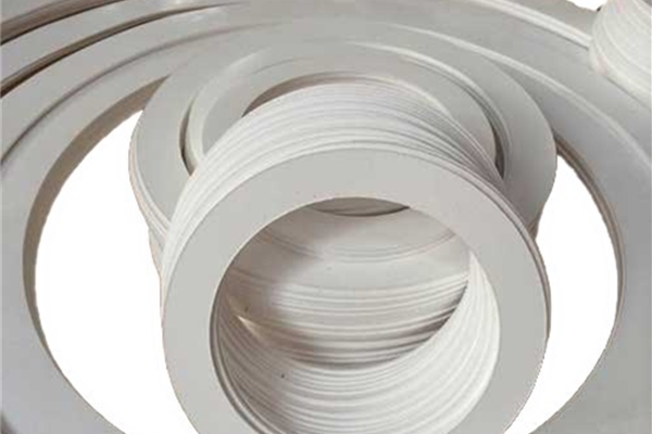
2.4 Aerospace Sealing
Aircraft contain numerous windows, hatches, and access panels requiring high-reliability seals. Traditional rubber seals compress well but age, lose elasticity, crack, and fail under thermal/UV stress. Fuel cap sealing with curing sealants involves complex application, long cure, and difficult removal during maintenance.
As a new fluoropolymer, ePTFE is increasingly used for structural seals in aerospace, offering:
Low density → meaningful weight savings; Broad service temperature range.
Excellent aging and creep resistance; Easy installation and maintenance.
Outstanding corrosion resistance. Components with very high sealing demands—service panels, forward bulkhead panels, lamp covers, cockpit windshields, radomes—historically used high-performance rubber O-rings that must be replaced at each disassembly (often costing thousands apiece). Switching to reusable ePTFE enables ≥ 50 disassemblies before replacement, raising maintenance efficiency and cutting cost dramatically—an irreplaceable advantage.
2.5 Medical Uses
ePTFE is an advanced medical polymer. Without carcinogenicity or sensitization, host cells and vasculature can ingrow into its micropores, forming biological integration—unlike silicone rubber, which relies on fibrous encapsulation. ePTFE is used successfully in aesthetic reconstruction, heart valve repair, vascular grafts, and obliteration of pulmonary residual cavities, and is considered an ideal soft-tissue substitute.
2.6 Other Fields
Except for the above, ePTFE has significant growth potential:
Laminated filtration media: ePTFE membranes on traditional substrates yield composite filter materials with superior fine-particulate control for industrial emissions.
Clean energy: often used as proton exchange membranes in fuel cells.
CO₂ capture, gas/vapor separations, and solvent filtration are additional use cases.
3. Conclusions
By modifying PTFE’s structure, ePTFE preserves PTFE’s core strengths while overcoming its weaknesses—enhancing comprehensive performance and expanding applications. Yet ePTFE manufacturing still faces technical challenges. Today, guidance literature is limited, standards are not unified, and marketed materials vary in quality. Future work should deepen understanding of the structure–property relationship, optimize production processes, and advance standardization—all of which have practical importance for the industry.
As material science and processing improve, ePTFE applications will extend far beyond those mentioned here. We expect new application pathways to emerge, with ePTFE exerting an even broader impact across industries