In many plants, sealing materials are still made from single-material fluoroplastics (e.g., PTFE, FEP), asbestos rubber sheet, or silicone rubber—converted into gaskets, washers, and packings. However, asbestos rubber and silicone rubber gaskets/washers/packings suffer from random filler distribution, strength that is directional rather than omnidirectional, poor anti-creep behavior, fast ageing, and short service life.
There was a PTFE composite for oil seals (per 100 parts by weight of suspension PTFE: MoS₂ 5.8–6.8, glass fiber 8.7–20.5, graphite 2.7–5.8). Yet materials of this type still exhibit insufficient wear resistance, thermal conductivity, high-speed capability, and anti-creep performance, leading to short life, hardening, and unsuitability for high-speed dynamic sealing.
Graphite-filled PTFE fiber packing addresses these weaknesses—delivering improved wear resistance, heat dissipation, high-speed performance, and low creep—so it can be used reliably in dynamic, high-speed sealing.
What Is Graphite PTFE Packing?
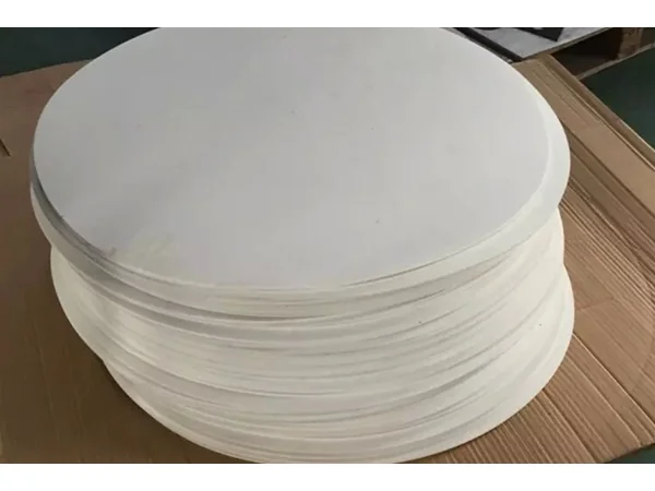
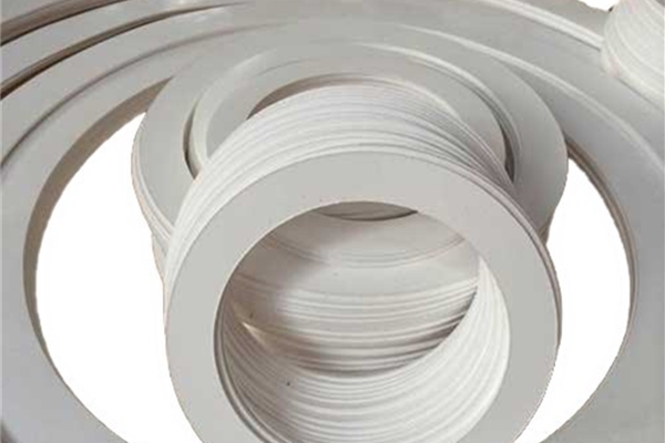
This packing is produced by incorporating natural graphite into PTFE resin, then extruding to form fibrillated PTFE, crystallizing/orienting to obtain soft fiber bundles, and finally braiding them into packing.
Typical composition (mass%): 50–82% PTFE dispersion resin; balance natural graphite.
The PTFE–graphite blend is conditioned at 30–100 °C for 2–15 h to promote intimate integration. The addition of ultrafine graphite overcomes the drawbacks of virgin PTFE, yielding excellent thermal conductivity, high-speed capability, low creep, broad chemical resistance, and a wider temperature window than pure PTFE. Using dispersion-polymerized PTFE with natural graphite increases pliability and helps prevent fracture in service.
A representative formulation contains 56% PTFE resin with the balance graphite, producing low friction, efficient heat transfer, and minimal creep relaxation.
Why It Outperforms Traditional Braided Packings
Thermal conductivity: Graphite pathways conduct heat away from the sealing interface, stabilizing temperature under high shaft speeds.
High-speed capability: Low friction (μ ≤ 0.12) and good heat dissipation support surface speeds of 2–25 m/s.
Low creep/anti-extrusion: Fibrillated PTFE matrix with graphite reduces cold flow, maintaining gland load and seal integrity.
Broad chemical resistance: Resistant to most media across process industries; wider service window than virgin PTFE.
Self-lubrication & long life: Graphite and PTFE provide inherent lubricity; no flush is required in many services; and there is no hardening tendency typical of inferior compounds.
Temperature capability: Continuous service ≤ 280 °C (per data below).
Verified Properties & Operating Limits
Composition (example): PTFE dispersion 50%, ultrafine natural graphite 38% (balance process aids).
Loss on heat (thermal mass loss): ≤ 11%
Coefficient of friction: ≤ 0.12
Wear loss: ≤ 0.02 g
Compressibility: 10–30%
Recovery: ≥ 25%
Max service temperature: ≤ 280 °C
Max pressure: Pumps 3 MPa; reciprocating rods 15 MPa; valves 25 MPa
Surface speed: 2–25 m/s
Packed density (braided): > 1.4 g/cm³
These figures are indicative of the technology described and guide engineering selection for pumps, valves, and reciprocating equipment.
Manufacturing Process — From Compound to Braided Packing
1) Mixing & conditioning
Sieve the mixture of natural graphite and polytetrafluoroethylene through a 20–30 mesh sieve, prepare the ingredients according to requirements, mix evenly, and blend using a mixer for 10–60 minutes; then place the mixed material in an oven for aging at 30–100°C for 2–15 hours.
2) Performing
Perform the blend using a hydraulic ram press.
3) Extrusion
Extrude on a hydraulic ram extruder; die outlet temperature 50–200 °C to form continuous tape/fibrillated strand.
4) Calendering
Process on a two-roll mill at 50–200 °C; obtain film/tape thickness 0.06–0.10 mm, width 25–500 mm.
5) Stretching & setting
Stretch on a dedicated stretcher at 120–300 °C to develop the node-and-fibril structure and dimensional stability.
6) In-line compounding/lamination
On a laminator, add graphite powder, silicone oil, and sealant between two PTFE films to form a composite tape with enhanced lubricity and sealing properties.
7) Slitting, folding & winding
Convert the composite into the required tapes/strands, fold where required, and wind to braiding packages.
8) Braiding
Using 24- or 36-carrier braiders (per size), braid graphite-filled PTFE fiber tapes (e.g., 3 g/m or 2 g/m) into square or cross-sectional packings; target density > 1.4 g/cm³.
Where to Use Graphite PTFE Packing
Centrifugal and rotary pumps handling chemicals, solvents, hydrocarbon fractions, and slurries within speed/pressure limits.
Valves requiring low friction start-up torque and high chemical resistance.
Reciprocating services where anti-creep and heat dissipation extend gland life.
High-speed dynamic sealing that would harden or rapidly wear conventional packings.